前言
本篇对Paint的一些常用方法和具有特殊效果的几个方法做一下的总结。
主要围绕以下几点展开说明:
- 基础使用
- 颜色
- setXfermode()方法
- 文本
基础使用
setAntiAlias(boolean aa)
该属性在上文 《自定义View之Canvas.drawXXX()》中也有说明。
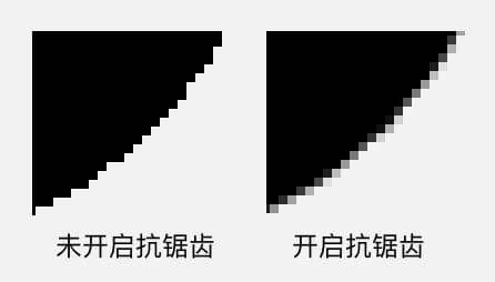
抗锯齿。让图形和文字的边缘更加平滑。
也可在 new Paint() 的时候加上一个 Paint.ANTI_ALIAS_FLAG 参数,进行设置。
1 | Paint paint = new Paint(Paint.ANTI_ALIAS_FLAG); |
锯齿出现的主要原因是屏幕的分辨率过低,使得绘制的边缘出现颗粒化。抗锯齿效果是修改图形边缘处的像素颜色,从而让图形在肉眼看来具有更加平滑的感觉。
setStyle(Style style)
设置画笔样式,系统提供了3种:
- Paint.Style.FILL :0,填充模式,是paint的默认模式
- Paint.Style.STROKE :1,画线模式
- Paint.Style.FILL_AND_STROKE :2,填充完后画线
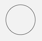
所以drawCircle时,paint为STROKE样式,则画出来的是一个圆环。
1 | paint.setStyle(Paint.Style.STROKE); // Style 修改为画线模式 |
FILL_AND_STROKE样式,相当于是先FILL模式绘制,再STROKE模式绘制。可以通过设置setStrokeWidth(float width)来设置一个较大的线条宽度来查看效果。
线条形状
设置线条形状的一共有 4 个方法:setStrokeWidth(float width), setStrokeCap(Paint.Cap cap), setStrokeJoin(Paint.Join join), setStrokeMiter(float miter) 。
这4个方法都需要在setStyle(Style style)为STROKE或FILL_AND_STROKE模式下有效。
setStrokeWidth(float width)
设置线条的宽度。
当传入width=0时,宽度永远为1像素,不会因为matrix的作用而改变宽度大小。
setStrokeCap(Cap cap)
设置线头形状,系统提供了三种:
1 | /** |
当线条宽度较细时,效果不明显,或者是没有效果(比如宽度为1时)。
下方是三者效果演示:
1 | mPaint = new Paint(Paint.ANTI_ALIAS_FLAG);//画线用 |
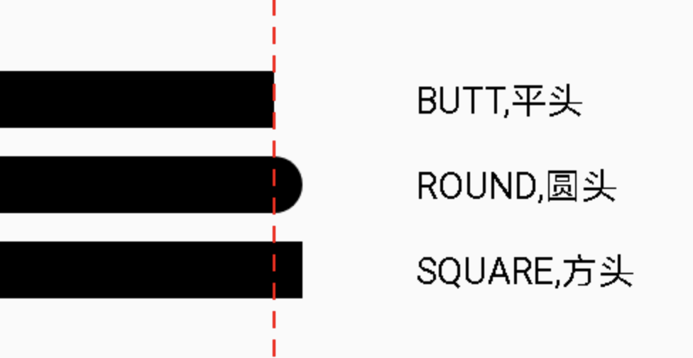
虚线左边是线的实际长度,虚线右边是线头。有了虚线作为辅助,可以清楚地看出 BUTT 和 SQUARE 的区别。
setStrokeJoin(Join join)
设置拐角连接处形状。
系统提供了3种:
1 | /** |
具体效果如下:
1 | mPaint = new Paint(Paint.ANTI_ALIAS_FLAG); |
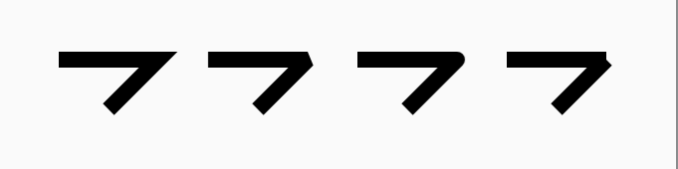
从左到右依次为:尖角,平角,圆角,两线段
setStrokeMiter(float miter)
在setStrokeJoin()为MITER时,设置尖角的最大延长值。当超过这个值时,剩余的延长线用BEVEL模式直接截断。
其中参数miter的计算如下:
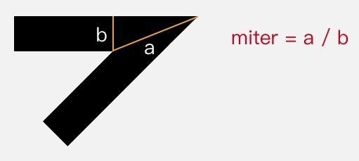
即:miter = 1 / sin ( θ / 2 ) 。其中θ为两遍夹角。
简单来讲就是:miter值越大,在夹角越小的情况下就越不会被截。
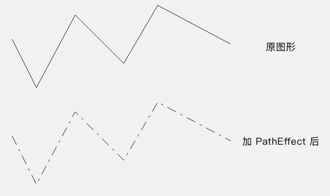
setPathEffect(PathEffect effect)
设置图形显示效果。
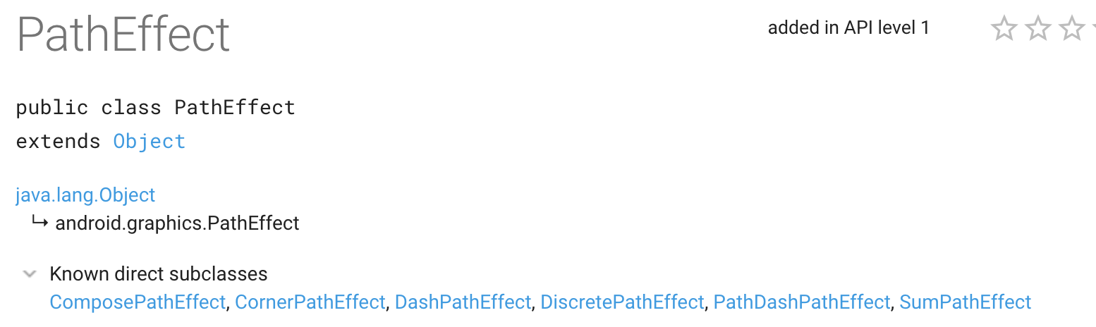
PathEffect有6个子类,可以简单分为两类:
- 单一效果
- CornerPathEffect 线段转角处用圆角过度
- DiscretePathEffect 把线条进行随机的离散
- DashPathEffect 用虚线来绘制线条
- PathDashPathEffect 用Path 来绘制「虚线」
- 组合效果
- SumPathEffect 用两种效果来分别绘制
- ComposePathEffect 用两种效果组合成一种组合效果绘制
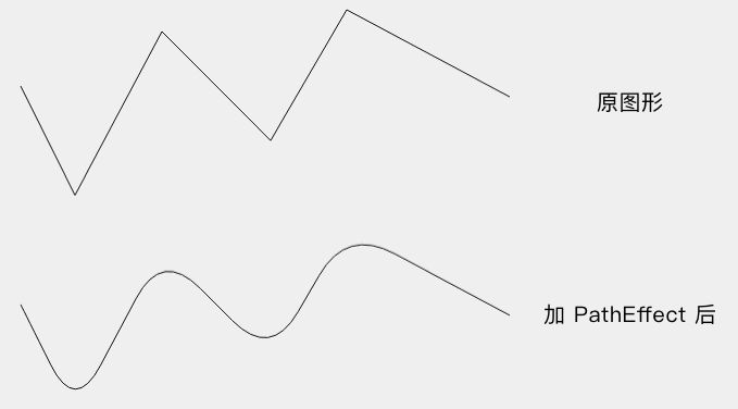
CornerPathEffect
线段转角处用圆角过度
构造方法
1 | CornerPathEffect(float radius) |
通过radius参数为圆角半径,用于控制转角处用圆角效果。radius越大,圆角越大越明显。
1 | PathEffect pathEffect = new CornerPathEffect(20); |
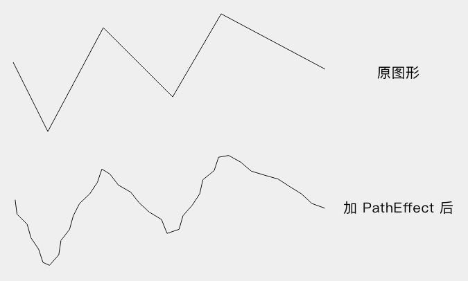
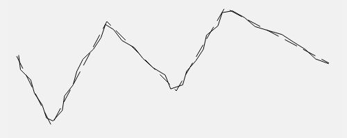
DiscretePathEffect
把线条进行随机的离散。
构造方法
1 | DiscretePathEffect(float segmentLength, float deviation) |
- segmentLength:线段长度
- deviation:偏离量
DiscretePathEffect效果即:用segmentLength长度的线段并随机偏移从而拼成原大致图形,线段的离散偏移由deviation的大小决定。
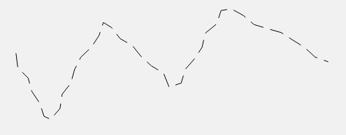
DashPathEffect
用虚线绘制图形。
构造方法
1 | DashPathEffect(float intervals[], float phase) |
- intervals 间隔数组,即虚线的样式,数组长度必须是非0偶数。数组下标为偶数的为绘制线段的长度,奇数则为空格的长度。
- phase 偏移量,
- 正数:在0的基础上,虚线的绘制效果往左移动phase个长度
- 负数:在0的基础上,虚线的绘制效果往右移动phase个长度
类似于phase=0时,数组为[1,2,3,4,5,6]
phase=2时,数组为[3,4,5,6,1,2]
phase=-2时,数组为[5,6,1,2,3,4]
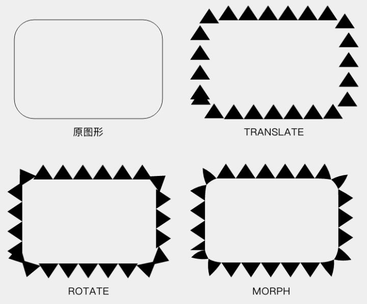
PathDashPathEffect
在DashPathEffect的基础上使用自定义的path来绘制DashPathEffect中的横线。
构造方法
1 | PathDashPathEffect(Path shape, float advance, float phase, Style style) |
- shape :自定义的path用来绘制DashPathEffect中的横线
- advance :两个相邻的 shape 段起点之间的间隔
- phase :偏移量,同DashPathEffect种的一致
- style :指定拐弯改变的时候 shape 的转换方式,是PathDashPathEffect内的一个美枚举类型,有3个:
- TRANSLATE :位移
- ROTATE :旋转
- MORPH :变体
1 | mPaint = new Paint(Paint.ANTI_ALIAS_FLAG); |
其中的close()方法的效果在 《自定义View之Path》中有具体说明,用于封闭当前子图形,相当于lineTo(起点坐标) 。
SumPathEffect
构造方法
1 | SumPathEffect(PathEffect first, PathEffect second) |
分别用first、second两种效果绘制,绘制结果是:first效果的一个图形 + second效果的一个图形。
1 | PathEffect dashEffect = new DashPathEffect(new float[]{20, 10}, 0); |
ComposePathEffect
构造方法
1 | ComposePathEffect(PathEffect outerpe, PathEffect innerpe) |
e.g. outer(inner(path))
是innerpe和outerpe两种效果的组合结果,在innerpe效果的基础上使用outerpe效果绘制。
1 | PathEffect dashEffect = new DashPathEffect(new float[]{20, 10}, 0); |
setDither(boolean dither)
设置是否使用图像抖动。false:取消抖动;true:设置抖动。
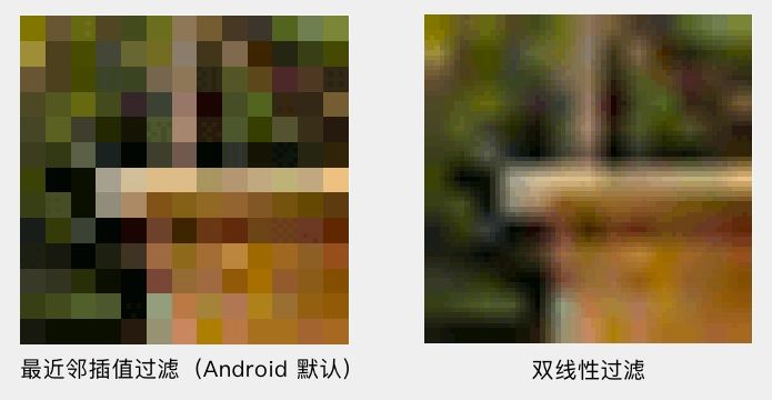
setFilterBitmap(boolean filter)
设置是否使用双线性过滤来绘制 Bitmap 。
图像在放大绘制的时候,默认使用的是最近邻插值过滤,这种算法简单,但会出现马赛克现象;而如果开启了双线性过滤,就可以让结果图像显得更加平滑。
setShadowLayer(float radius, float dx, float dy, int shadowColor)
在绘制内容下添加阴影效果。
各参数作用:
- radius:阴影半径;值越大,阴影延伸越多。radius=0时,不绘制阴影效果。
- dx:阴影x轴方向偏移量
- dy:阴影y轴方向偏移量
- shadowColor:阴影颜色
官方注释:
1 | /** |
其中提到了以下几点:
- radius=0时,取消阴影效果
- 文本都可以使用阴影效果
- 文本外的其他图形,如果需要使用阴影效果,必须关闭硬件加速
- 阴影透明度值的来源:参数shadowColor中不带透明度时,使用画笔中的透明度;参数shadowColor中带透明度时,使用shadowColor中的透明度
如果要清除阴影层,使用 clearShadowLayer() 。
1 | /** |
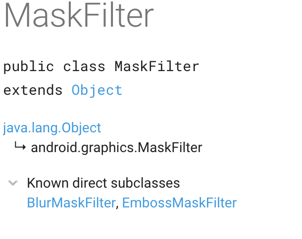
setMaskFilter(MaskFilter maskfilter)
为之后的绘制设置 MaskFilter。上一个方法 setShadowLayer() 是设置的在绘制层下方的附加效果;而这个 MaskFilter 和它相反,设置的是在绘制层上方的附加效果。
该属性需要关闭硬件加速,才能有效果。
MaskFilter有两个子类:BlurMaskFilter, EmbossMaskFilter
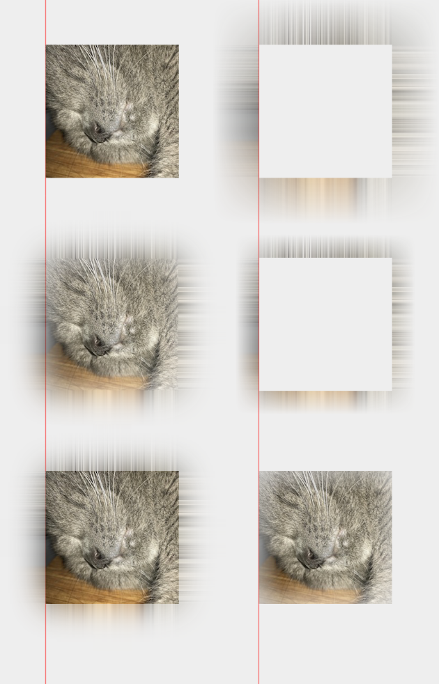
BlurMaskFilter(float radius, Blur style)
模糊效果。
参数说明
- radius:模糊的半径(值越大,模糊范围越大)
- style:模糊类型,共4种
- NORMAL:内外都模糊绘制,内部颜色变淡
- OUTER:内部不绘制,外部模糊
- INNER:内部模糊,外部不绘制
- SOLID:内部正常绘制,外布模糊
1 | mPaint = new Paint(Paint.ANTI_ALIAS_FLAG); |
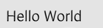
EmbossMaskFilter(float[] direction, float ambient, float specular, float blurRadius)
设置浮雕效果。Api28开始deprecated(不推荐使用)。
- direction:3个数据的数组,[x,y,z],代表光照方向。
- ambient:环境光的强度,数值范围是 0 到 1
- specular:炫光系数,例如:8
- blurRadius:照明前的模糊量,例如:3
1 | mTextPaint = new Paint(Paint.ANTI_ALIAS_FLAG); |
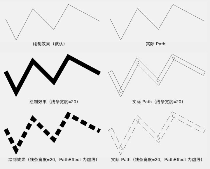
getFillPath(Path src, Path dst)
获取src的实际path dst;
所谓实际 Path ,指的就是 drawPath() 的绘制内容的轮廓,要算上线条宽度和设置的 PathEffect。
方法的参数里,src 是原 Path ,而 dst 就是实际 Path 的保存位置。 getFillPath(src, dst) 会计算出实际 Path,然后把结果保存在 dst 里。
该方法返回结果为boolean类型。true:填充dst;false:dst宽度为0(发际线)。
1 | /** |
getTextPath(String text, int start, int end, float x, float y, Path path) / getTextPath(char[] text, int index, int count, float x, float y, Path path)
获取「文字的 Path」。
文字的绘制,虽然是使用 Canvas.drawText()方法,但其实在下层,文字信息全是被转化成图形,对图形进行绘制的。 getTextPath() 方法,获取的就是目标文字所对应的 Path 。这个就是所谓「文字的 Path」。
颜色
setColor(@ColorInt int color)、setARGB(int a, int r, int g, int b)、setAlpha(int a)
直接设置颜色。setARGB()与setAlpha()的参数取值范围为[0,255]。
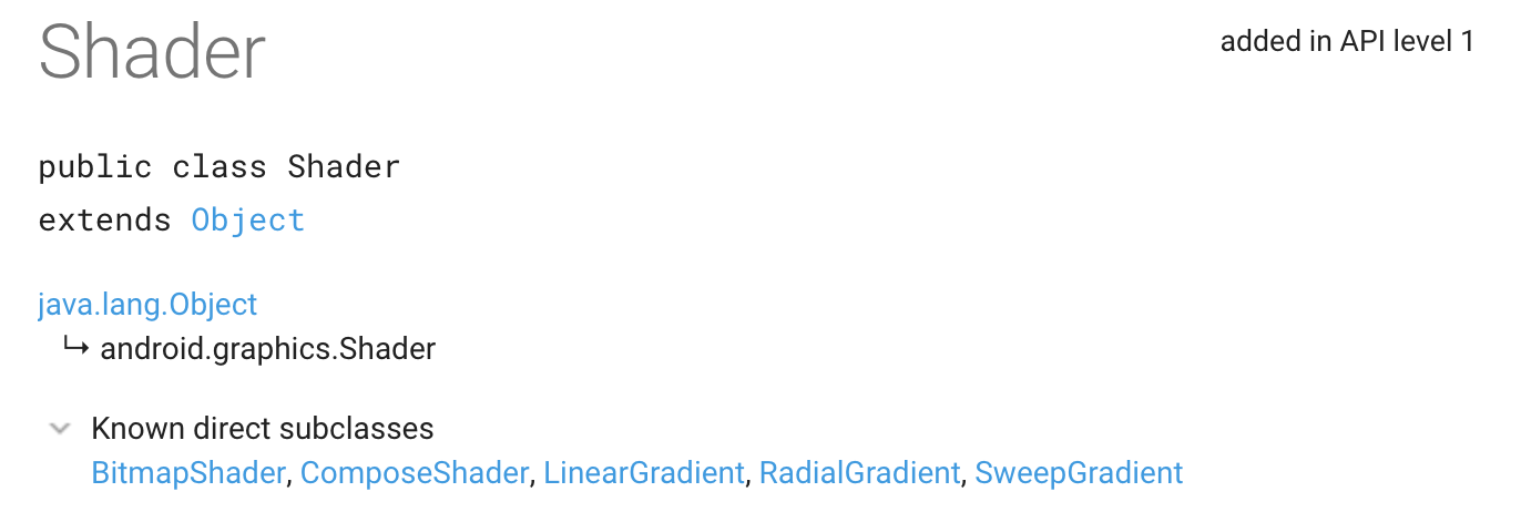
setShader(Shader shader)
设置着色器。
参数shader为null时,用于清除之前设置的shader效果。
这里并非直接使用shader类,而是使用它的子类。
shader有5个直接子类:BitmapShader, ComposeShader, LinearGradient, RadialGradient, SweepGradient
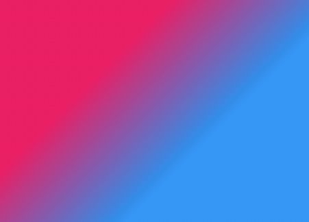
LinearGradient
线性渐变效果。有两个构造方法:
- LinearGradient(float x0, float y0, float x1, float y1, @NonNull @ColorInt int colors[], @Nullable float positions[], @NonNull TileMode tile)
- LinearGradient(float x0, float y0, float x1, float y1, @ColorInt int color0, @ColorInt int color1, @NonNull TileMode tile)
两构造方法参数相同之处:
- x0, y0:线性渐变开始坐标
- x1, y1:线性渐变结束坐标
- tile:用于处理处理x0, y0和 x1, y1之外的颜色效果。共3种类型,在下面会详细介绍。
不同之处:
第一个构造方法:
- colors[]:整形数组,用于存放各个颜色
- positions[]:用于设置对应colors[]中位置处颜色的相对位置,取值范围[0,1]。当该参数为null时,colors[]中的颜色在渐变过程中均匀出现。
比如:
1 | int[] colors = {Color.GRAY, Color.RED, Color.YELLOW}; |
其中的positions代表:
在当前view坐标内的(0,0)到(mViewWidth,0)中,在20%处为GRAY,40%处为RED,80%处为YELLOW。
第二个构造方法:
- color0:渐变开始颜色
- color1:渐变结束颜色
也就是说第二个构造方法只有2种颜色,第一个构造方法可以指定数个渐变颜色。
TileMode的3种类型:
1 | public enum TileMode { |
| CLAMP | REPEAT | MIRROR |
|---|---|---|
 |
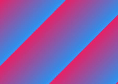 |
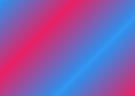 |
LinearGradient可以用于TextView文本的闪动效果。
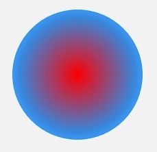
RadialGradient
从中心辐射。
构造方法:
- RadialGradient(float centerX, float centerY, float radius, @NonNull @ColorInt int colors[], @Nullable float stops[], @NonNull TileMode tileMode)
- RadialGradient(float centerX, float centerY, float radius, @ColorInt int centerColor, @ColorInt int edgeColor, @NonNull TileMode tileMode)
与LinearGradient类似,其中第一个构造方法中的参数stops相当于LinearGradient中的positions。
1 | Shader shader = new RadialGradient(300, 300, 200, Color.parseColor("#E91E63"), |
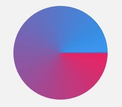
SweepGradient
绕指定中心点,扫描渐变。
构造方法:
- SweepGradient(float cx, float cy, @NonNull @ColorInt int colors[], @Nullable float positions[])
- SweepGradient(float cx, float cy, @ColorInt int color0, @ColorInt int color1)
其中第一个构造方法中的参数colors[],positions[]与LinearGradient中的同名参数作用一致。
cx, cy为扫描中心点。
1 | shader = new SweepGradient(300, 300, Color.parseColor("#E91E63"), |
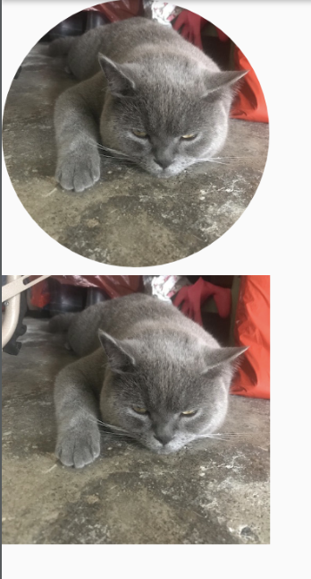
BitmapShader
用 Bitmap 来着色。其实也就是用 Bitmap 的像素来作为图形或文字的填充。
1 | int radius = mBitmap.getWidth() / 2; |
ComposeShader
使用两种shader混合绘制。
构造方法:
- ComposeShader(@NonNull Shader shaderA, @NonNull Shader shaderB, @NonNull Xfermode mode)
- ComposeShader(@NonNull Shader shaderA, @NonNull Shader shaderB, @NonNull PorterDuff.Mode mode)
这两个构造方法前两个参数一致,代表连个Shader。
第三个参数代表混合的模式,这个在下一节中详细展开介绍。
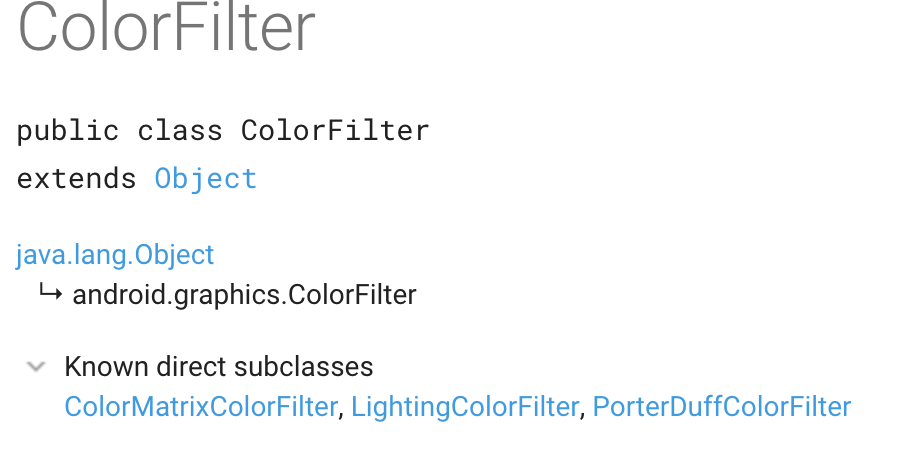
setColorFilter(ColorFilter colorFilter)
设置颜色过滤。
参数ColorFilter不能直接使用,但它有3个直接子类:ColorMatrixColorFilter, LightingColorFilter, PorterDuffColorFilter。
ColorMatrixColorFilter
通过一个4x5的颜色矩阵,过滤颜色。
可以用于设置饱和度、YUV转换成RGB等等,具体功能同ColorMatrix类。
ColorMatrix内有一个长度为20的浮点数组,即4x5的颜色矩阵。
1 | [ a, b, c, d, e, |
对于颜色 [R, G, B, A] ,转换算法是这样的:
1 | R’ = a*R + b*G + c*B + d*A + e; |
[R’, G’, B’, A’]则为新的颜色。
比如通过ColorMatrix设置灰白图片:
1 | ColorMatrix colorMatrix = new ColorMatrix(); |
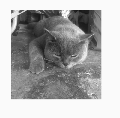
其他的设置可以查看开源项目StyleImageView。
LightingColorFilter
模拟简单的光照效果。
LightingColorFilter 的构造方法是 LightingColorFilter(int mul, int add) ,参数里的 mul 和 add 都是和颜色值格式相同的 int 值,其中 mul 用来和目标像素相乘,add 用来和目标像素相加,最终的[R’,G’,B’]值范围均限定在[0,255]内。
1 | R' = R * mul.R / 0xff + add.R |
PorterDuffColorFilter
构造方法为PorterDuffColorFilter(@ColorInt int color, @NonNull PorterDuff.Mode mode)。
PorterDuffColorFilter通过mode模式将color作用到原像素上。
setXfermode(Xfermode xfermode)
其中“X”表示“Trans”,所以“Xfermode”即“Transfermode”,转换方式。
用于设置处理将源像素(source pixels)合并到目标像素(destination pixels)的不同算法。
参数xfermode为null时,用于清除之前设置的xfermode。
目标像素:画布上已有内容
源像素:将要绘制的内容
目前,Xfermode的子类只有PorterDuffXfermode。AvoidXfermode、PixelXorXfermode已经废弃。
PorterDuffXfermode的构造方法为PorterDuffXfermode(PorterDuff.Mode mode),通过参数设置mode。
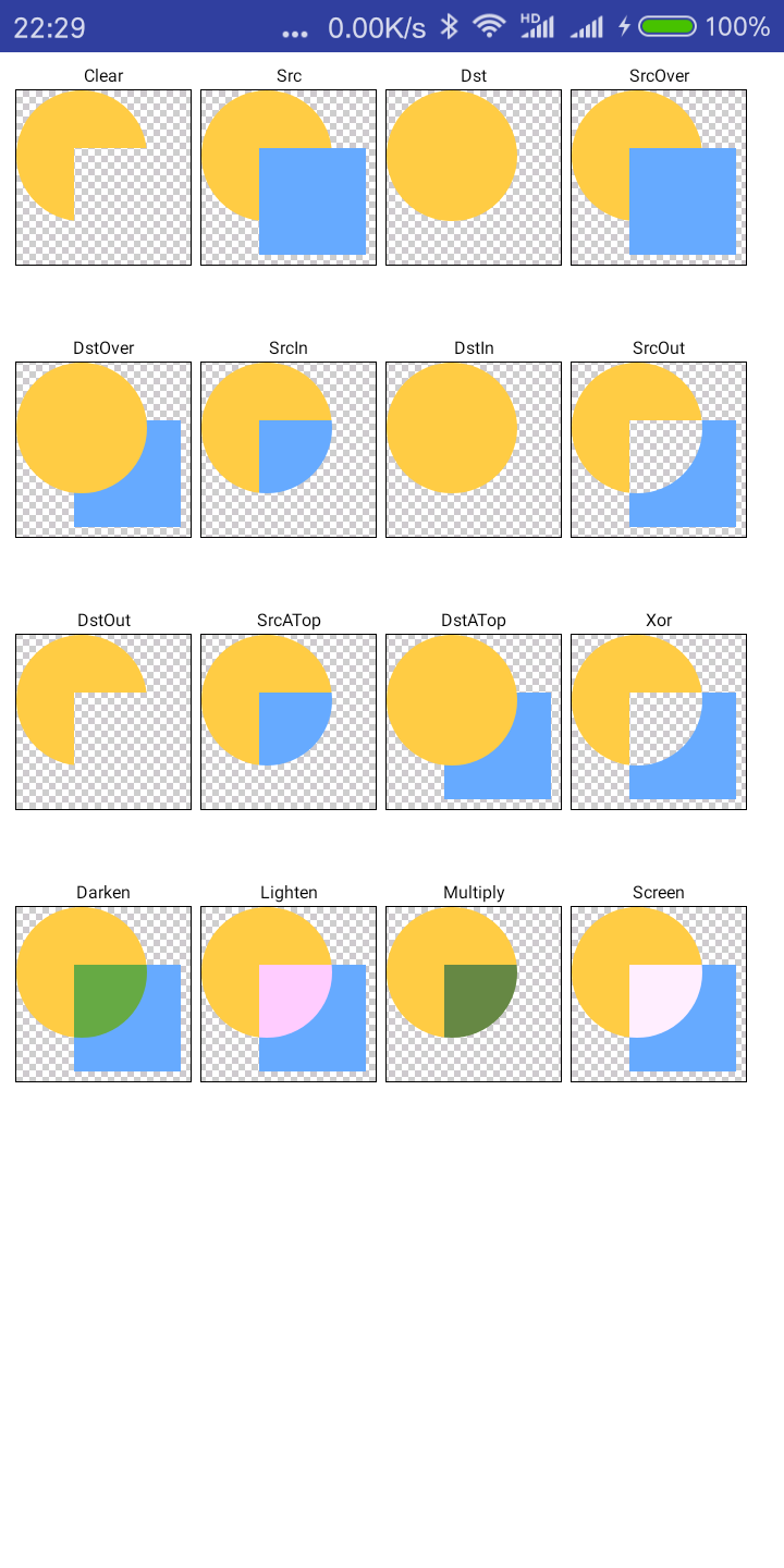
PorterDuff.Mode有如下几种:
CLEAR、SRC、DST、SRC_OVER、DST_OVER、SRC_IN、DST_IN、SRC_OUT、DST_OUT、SRC_ATOP、DST_ATOP、XOR、DARKEN、LIGHTEN、MULTIPLY、SCREEN。
下图中:Sa,Sc,Da,Dc中的S、D、a、c分别表示source、destination、alpha、color,所以
Sa全称为Source alpha表示源图的Alpha通道;
Sc全称为Source color表示源图的颜色;
Da全称为Destination alpha表示目标图的Alpha通道;
Dc全称为Destination color表示目标图的颜色.
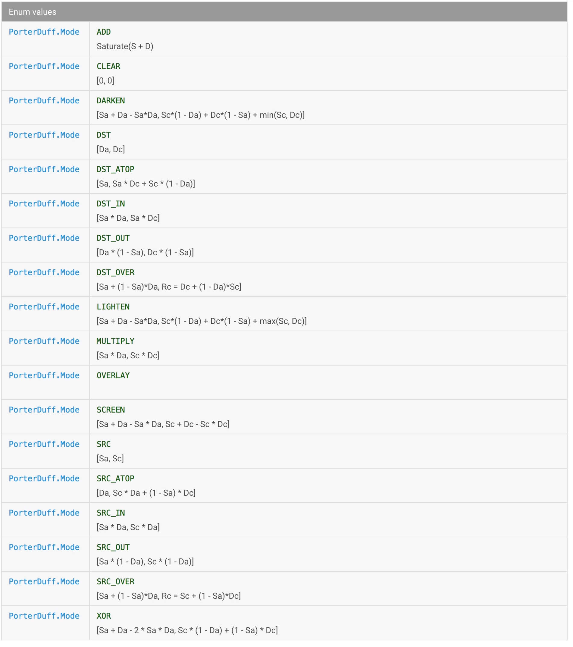
上图中“[,]”,表示的是混合后图片的计算方式,其中“,”前面的为alpha通道,“,”后面的是颜色。
示例代码:
1 | public class Xfermodes extends Activity { |
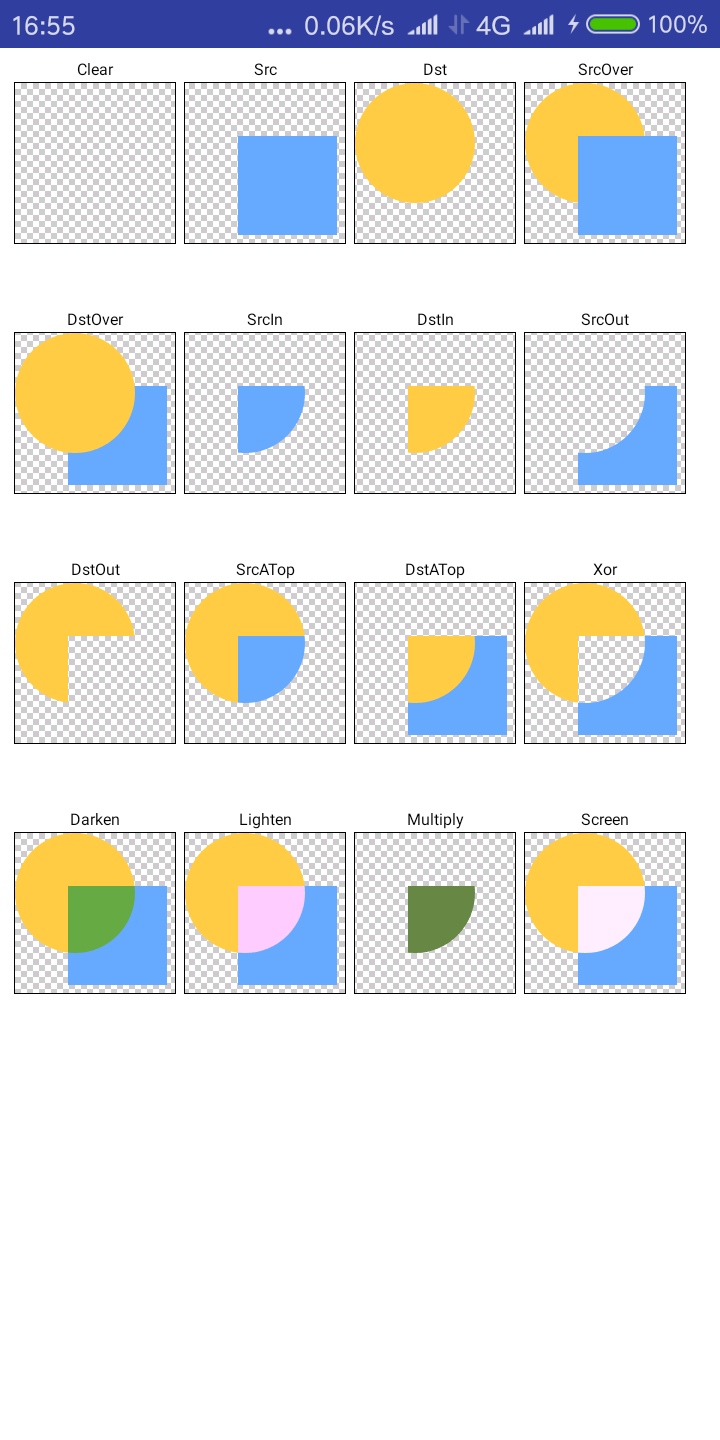
上图为上面示例代码的运行效果,与官方文档中的效果一致。
上图中灰白相间的背景是为了方便用户查看而刻意通过BitmapShader绘制上去的。
不过请注意看其中makeDst(int w, int h)和makeSrc(int w, int h)两个方法,方法内先以w、h创建bitmap,但是bitmap的内容只有其中一部分c.drawOval(new RectF(0, 0, w * 3 / 4, h * 3 / 4), p);、c.drawRect(w / 3, h / 3, w * 19 / 20, h * 19 / 20, p);,所以上图中的src和dst两个图就是mSrcB和mDstB连个bitmap的显示效果,其中灰白相间的背景所覆盖的范围就是mSrcB和mDstB的大小。
注:调用Canvas.saveLayer()方法,用做短时的离屏缓冲(offscreen)。相当于photoshop中的涂层。绘制完成后调用Canvas.restoreToCount()。
调整上述代码:
1 | public class MyXfermodes extends AppCompatActivity{ |
代码中改动如下:
makeDst(int w, int h)和makeSrc(int w, int h)两个方法中的内容占满w,h- 调用
makeDst()和makeSrc()两个方法时,参数大小调整 - 绘制mSrcB时调整位置
可以看到上图与没改动前只有一个差别,就是dst圆形未与src方形相交的部分一直显示。也就是说未相交部分不参与计算,所以不会变化。